Gyro Stabilization in PTZ and Gimbal Cameras: A Comprehensive Overview
Gyro Stabilization for Advanced PTZ Camera Systems by SPI
The necessity of image stabilization becomes paramount for extended-range PTZ camera applications due to the magnified effects of camera shake in long-range imaging. The urgency for superior stabilization solutions is directly linked to the camera’s field-of-view and the probable camera shake it might experience.
Tiny Vibrations are Exaggerated in Long‑Range Captures
Many ponder why there’s a need for gyro stabilization when everyday cameras, such as smartphones or action cameras, can produce clear images without it. The answer lies in the field of view. A standard smartphone boasts a broad field of view (60°), and an action camera extends to an even wider 120°. If a jolt causes a 2° shake, a smartphone’s image will shift by 3% while an action camera’s by 1.5%. In contrast, SPI’s long-distance zoom cameras often possess fields of view narrower than 1°. A mere 2° shake can cause a staggering 200% image shift for such cameras.
Smartphones Use EIS – What is it?
Smartphones and EIS: An In-depth Look
Introduction
Electronic Image Stabilization (EIS) has rapidly become one of the go-to technologies for modern smartphones, aiming to produce steady and blur-free video footage even when the camera or subject is in motion. But what is EIS, how does it work, and how is it different from other stabilization techniques? Let’s dive in.

What is EIS?
Electronic Image Stabilization (EIS) is a method used to stabilize video footage digitally, rather than mechanically. While traditional stabilization methods, like Optical Image Stabilization (OIS), rely on moving parts within the camera to counteract unintentional movements, EIS does this by processing the video data after it has been captured.
How Does EIS Work?
- Frame Analysis: When recording video, the camera captures a series of frames. EIS algorithms analyze these frames to detect unwanted movement or shakes.
- Frame Cropping: After detecting movement, EIS crops each frame slightly. This “crop margin” allows the software to adjust the position of each frame to counteract the shake.
- Frame Repositioning: Based on the detected movement, each frame is shifted or repositioned to align better with the previous frame, ensuring smooth transitions and reducing shake.
- Compensation for Rolling Shutter: Many smartphone cameras use a rolling shutter mechanism, which can cause distortions, especially during fast movements. EIS algorithms also work to correct these distortions.
Benefits of EIS
- No Mechanical Parts: EIS doesn’t require any moving parts, making it less prone to wear and tear and potentially increasing the lifespan of the camera system.
- Adaptability: Since EIS is software-based, improvements can be made via software updates, allowing for constant enhancements without needing to change the hardware.
- Cost-Effective: Integrating EIS can be less expensive than adding mechanical stabilization systems, which is why many budget smartphones opt for EIS.
The Boundary of Digital EIS Stabilization
With the rise of digital and electronic stabilization in modern tech, one might assume that such methods would suffice. However, for extended-range cameras with high optical zoom, digital solutions fall short without the backup of a mechanical gyro PTZ system. EIS (Electronic Image Stabilization) essentially works by contrasting video frames and adjusting for any abrupt shifts. This can result in unwanted cropped areas on the frame’s edges. While this might work for minor shifts, for displacements over 100%, EIS loses its effectiveness.
EIS vs. OIS: Delving Deeper with Long-Range Thermal Cameras
What is Optical Image Stabilization (OIS)?
Optical Image Stabilization (OIS) utilizes a physical mechanism to counteract unwanted camera movements. It adjusts the lens or the sensor itself in real-time. In contrast, Electronic Image Stabilization (EIS) is a post-capture digital correction process. It adjusts the video by cropping and repositioning frames to compensate for motion.
Application in Long-Range Thermal Cameras
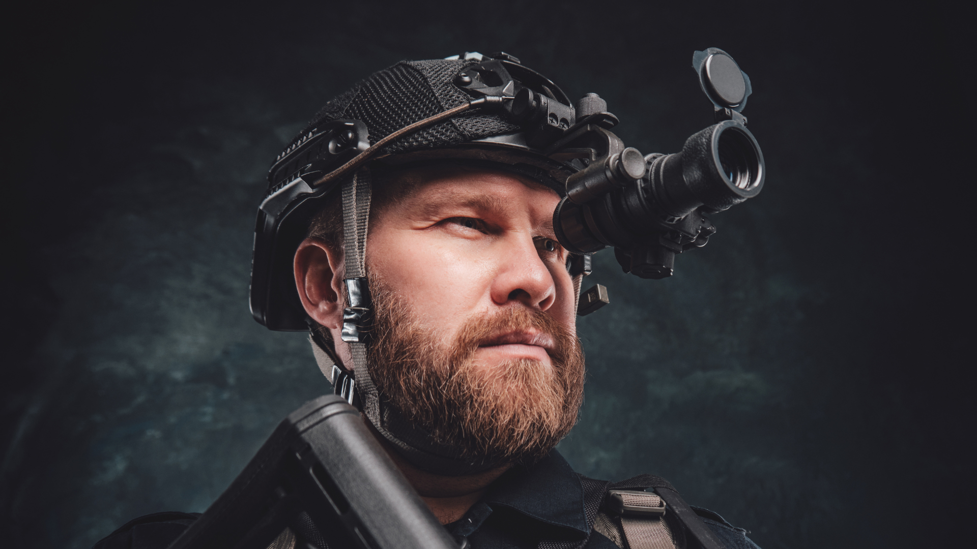
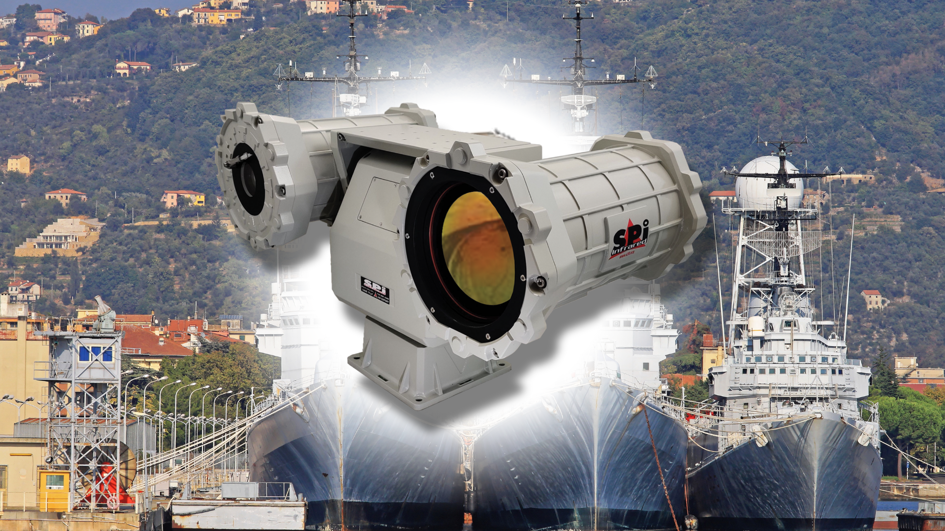
Long-range thermal cameras are typically used for specialized applications such as wildlife observation, border security, maritime surveillance, and more. Given the longer focal lengths and narrower fields of view involved, even minor vibrations can drastically affect image quality.
- Stabilization Efficiency: With long-range thermal imaging, the slightest movement can result in a substantial shift in the captured image. Here, OIS shines. The mechanical adjustments of OIS are precise and immediate, offering real-time compensation for any jitters. EIS, on the other hand, might struggle since post-capture adjustments have limitations, especially when it comes to significant shakes.
- Resolution Retention: In long-range thermal imaging, maintaining resolution is paramount. Since EIS involves cropping the video frame for stabilization, there’s an inherent resolution loss. For detailed thermal imaging where every pixel might count, this could be detrimental. OIS does not suffer from this drawback, as it stabilizes without compromising the original frame’s resolution.
- Low-Light Performance: Thermal cameras often operate in low-light conditions or even complete darkness. In such settings, OIS is particularly advantageous. It allows for longer exposure times without introducing blur, capturing clearer thermal signatures. EIS doesn’t aid in this aspect since it doesn’t affect the capture process directly.
- Integration and Cost: OIS, with its gyroscopes and motors, demands more intricate hardware design. This can make the cameras bulkier and more expensive. EIS, being software-driven, can be incorporated into a broader array of devices without significant hardware alterations. However, in specialized equipment like long-range thermal cameras, the cost difference might be justified by the performance gains.
So, Which is Better for Long-Range Thermal Cameras?
For critical applications that demand the utmost clarity, especially in challenging conditions, OIS is usually the preferred choice. Its real-time mechanical gyro stabilization ensures that the image remains sharp and detailed, even at significant zoom levels and in low-light conditions.
EIS can still be utilized as a supplementary stabilization method or in scenarios where the budget is a concern. However, given the inherent resolution loss and potential issues with significant vibrations, it might not be the first choice for professional-grade long-range thermal imaging.
The Mechanism Behind Gyro Stabilization
SPI employs advanced FOG (Fiber Optic Gyroscope), OIS, or MEMS (micro-electro-mechanical systems) gyroscope, fixed to the camera base, to detect any potential movements. Upon detecting movement, it instructs the pan/tilt unit to counteract by rotating the camera inversely. The effectiveness lies in the gyroscope’s precision, system latency, and the agility and accuracy of the pan/tilt motors. Given the intricacies involved, SPI offers tailored configurations to suit unique requirements.
It’s pivotal to assess the specifications of the pan/tilt while considering a gyro-stabilized system. Their performance varies, and the best fit depends on its intended use.
Technical Deep Dive into Gyro Stabilization OIS, MEMS, and FOG
Understanding Gyro Stabilization
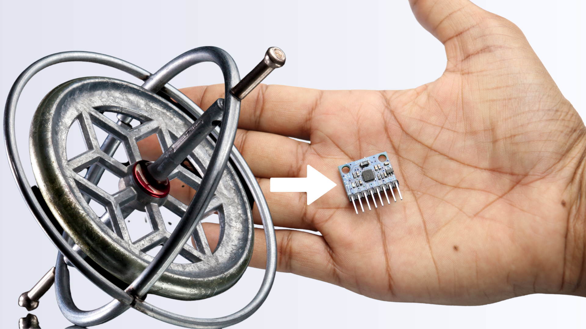
At its core, a gyroscope is a device that uses the principles of angular momentum to maintain orientation. It employs a rapidly spinning disc, called a rotor, which maintains its spin axis direction regardless of any movement in its base. In camera systems, gyroscopes help stabilize an image by counteracting unintentional camera movement, making the imagery steadier and more reliable.
Optical Image Gyro Stabilization (OIS):
Optical Image Gyro Stabilization (OIS) stands as a cornerstone technology in modern photography and videography, ensuring images and videos remain sharp and free from the blurs induced by handshakes or other unintended motions. Let’s delve deeper into the intricate science and mechanics behind this innovation.
Fundamental Principle: Gyroscopic Sensing
At the heart of OIS lies the gyroscope—a device that measures angular velocity. Modern cameras employ MEMS (Micro-Electro-Mechanical Systems) gyroscopes, which can detect even minute changes in orientation.
- Gyroscopic Feedback Loop: When motion is detected, the gyroscope generates an electrical signal proportional to the angular velocity.
- Signal Processing: This electrical signal is processed by the camera’s controller, which then determines how much, and in which direction, the lens or sensor should move to counteract the shake.
Mechanisms of OIS:
There are primarily two methods employed for OIS:
- Lens-based OIS: Here, specific lens elements within the lens assembly are shifted to counteract motion. This is common in standalone cameras and some smartphone cameras.
- Sensor-shift OIS: The entire image sensor is moved to compensate for the shake. This method is common in many DSLRs and mirrorless cameras.
Advanced OIS Techniques:
- Multi-axis Gyro Stabilization: While early OIS systems worked only in two axes (horizontal and vertical), advanced systems can correct for roll motion in addition to the standard pitch and yaw motions.
- Hybrid Gyro Stabilization OIS: This merges the benefits of both lens-based and sensor-shift stabilization. Here, both the lens and sensor are adjusted simultaneously, providing even more precise gyro stabilization, especially in macro photography where the depth of field is extremely shallow.
Physical Components Involved in OIS:
Voice Coil Motors (VCM): These are responsible for the rapid and precise movement of the lens or sensor. They translate the electrical signals from the gyroscope into mechanical movement.
- Floating Lens Elements: In lens-based OIS, specially designed lens elements “float” within the lens assembly. They can be rapidly moved to counteract shakes.
- Piezoelectric Actuators: In some advanced systems, piezoelectric actuators, which change shape when an electric current is applied, are used to move lens elements or sensors with high precision.
Challenges and Limitations:
- Physical Limits: There’s a limit to how far a lens element or sensor can be moved. In scenarios with excessive motion, the OIS may not be able to fully compensate.
- Latency: While modern systems are incredibly fast, there’s still a tiny delay between motion detection and compensation, which might impact extremely fast or sudden movements.
Scientific Aspects of OIS:
- Conservation of Angular Momentum: Gyroscopes operate based on the principle of conservation of angular momentum. They resist changes to their axis of rotation, which allows them to detect even minute angular shifts.
- Electromagnetic Induction: VCMs use electromagnetic fields to induce motion in the lens or sensor, offering precise, rapid adjustments.
FOG (Fiber Optic Gyroscope) Explained
The FOG is an advancement over traditional mechanical gyroscopes. Instead of relying on a spinning rotor, the FOG employs light. The device consists of a coil of optical fiber that exploits the interference of light to detect mechanical rotation.
How it Works: Light from a laser source splits into two beams, traveling in opposite directions through the coil. When the device rotates, it causes a slight change in the time it takes for the light beams to pass through the coil, known as the Sagnac effect. By measuring the interference pattern when the two beams recombine, the device can determine the rate of rotation.
Advantages: FOGs have no moving parts, leading to increased reliability and a longer operational lifespan. They’re also highly sensitive and can detect minute changes in rotation, making them particularly valuable for high-end applications where precision is crucial.
Limitations: Despite their sensitivity, FOGs can be affected by temperature changes, requiring additional components or systems for temperature compensation. They’re also typically more expensive than MEMS-based systems.
MEMS (Micro-Electro-Mechanical Systems) Gyroscopes
MEMS gyroscopes are micro-scale devices that measure rotational speed. They are the backbone of many consumer electronic devices like smartphones and tablets, providing them with orientation information.
How it Works: MEMS gyroscopes utilize tiny vibrating structures. When the gyroscope rotates, the Coriolis effect causes a tiny change in the vibration pattern. This change can then be measured electrically and is proportional to the rotational speed.
Advantages: MEMS gyroscopes are smaller, lighter, and more cost-effective than FOGs. They are also incredibly energy efficient, which makes them suitable for battery-powered applications. With advancements in technology, MEMS gyroscopes are steadily improving in terms of accuracy and sensitivity.
Limitations: They might not have the same level of precision as high-end FOGs, especially in extremely demanding applications. Also, their performance can degrade over time due to wear and tear on the microstructures.
Real-world Applications
Both FOG and MEMS technologies have found extensive application across various domains. For instance:
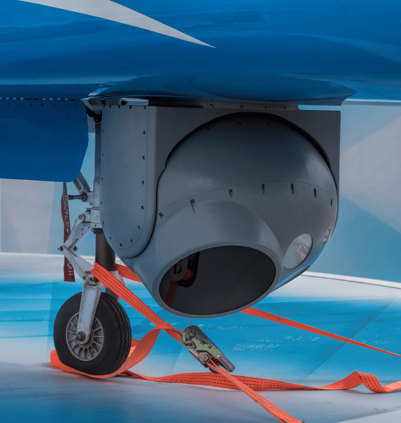
- Aviation: FOGs are commonly used in aircraft gyro stabilization systems due to their high precision and reliability.
- Consumer Electronics: MEMS gyroscopes are staples in devices like smartphones, gaming controllers, and virtual reality headsets, enabling motion tracking and orientation detection.
- Navigation: Both FOGs and MEMS play critical roles in modern navigation systems, ensuring accuracy in orientation and direction.
Which One to Choose?
When deciding between FOG and MEMS for a PTZ camera system, several factors come into play:
- Precision Needs: For ultra-high precision applications, FOG might be the preferred choice, while MEMS can suffice for standard requirements.
- Budget Constraints: MEMS gyroscopes are more budget-friendly, making them a suitable choice for projects with tight financial constraints.
- Size and Weight: If minimizing the footprint is crucial, MEMS, with its compactness, might be more suitable.
- Operational Lifespan: FOGs, with no moving parts, generally promise a longer lifespan compared to MEMS.
The Evolution of Gyro Stabilization: A Historical Perspective
The story of gyro stabilization is a fascinating journey, intertwining physics, innovation, and the relentless human pursuit to master our environment. Its history provides context to our modern-day reliance on this technology.
Ancient Beginnings
The roots of gyroscopic principles date back to ancient civilizations. The spinning top, a toy that has entertained children for millennia, behaves much like a gyroscope. It remains upright, resisting gravitational forces due to the conservation of angular momentum. Ancient Chinese and Greek civilizations observed this behavior, laying the foundational curiosity for future gyroscopic discoveries.
Serson’s Whirling Speculum
In the 18th century, British inventor John Serson introduced the “Whirling Speculum” or “Serson’s Speculum.” While it wasn’t a gyroscope in the modern sense, this device demonstrated principles of rotational physics. Serson used it to explain the precession of the equinoxes and other astronomical phenomena.
The Birth of the Modern Gyroscope
The term “gyroscope” was coined by French experimental physicist Léon Foucault in the mid-19th century. In 1852, Foucault used a gyroscope to demonstrate the Earth’s rotation. His device consisted of a rotor suspended in gimbals, which allowed it to rotate freely. As the Earth turned, the gyroscope’s direction of rotation remained constant, proving Earth’s movement.
20th Century: A Century of Innovation
The 20th century saw rapid advancements in gyroscopic technology, largely driven by military and aerospace applications.
- World War I: Gyroscopes were crucial for stabilizing guns on turbulent seas. The naval vessels used these systems to ensure accurate firing even when the ship rocked.
- World War II: The technology further evolved during the Second World War. The Germans developed the V-2 rocket, which utilized gyroscopes for gyro stabilization and guidance, marking a pivotal moment in the use of gyroscopes for missile technology.
- Aerospace and Space Exploration: The 1960s and 1970s saw the application of gyroscopes in space exploration. They played an essential role in the Apollo missions, helping to stabilize and orient spacecraft.
Gyro stabilization in Cameras
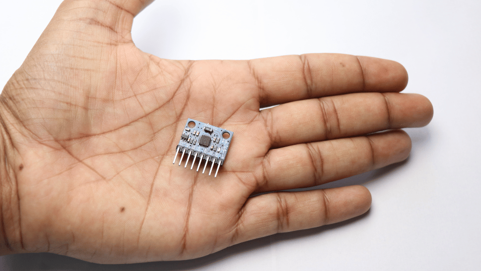
With the miniaturization of technology in the late 20th century, gyro stabilization made its way into commercial applications, notably cameras. Initially, this was limited to professional equipment, such as those used in filming from helicopters or capturing images from shaky platforms. However, with time, even personal handheld devices and drones began integrating miniaturized gyro-stabilizers, drastically improving image and video quality.
21st Century: The Digital Revolution
The advent of the digital age transformed gyro stabilization. While traditional gyroscopes relied on mechanical systems, the 21st century saw the rise of MEMS (Micro-Electro-Mechanical Systems) gyroscopes. These tiny, semiconductor-based devices offered a cheaper, smaller, and more energy-efficient way to achieve stabilization. Today, they’re ubiquitous, found in everything from smartphones to gaming controllers.
In the realm of cameras, digital technology introduced Electronic Image Stabilization (EIS), which uses algorithms to correct shake. However, as highlighted in previous sections, for certain applications, especially long-range imaging, mechanical stabilization, as offered by gyroscopes, remains unparalleled.
The Future of Gyro Stabilization
As technology progresses, the boundaries between different types of gyroscopes might blur. Hybrid systems, combining the best features of FOG and MEMS, might emerge, offering enhanced performance at a reduced cost. Additionally, with the advent of quantum technologies, even more advanced gyroscopes leveraging quantum principles might revolutionize the stabilization field.
Applications
Airport Observation Towers & High Structures
Even solid structures like towers aren’t always entirely stable. For instance, the Eiffel Tower’s tip can sway up to seven meters in windy conditions. For such applications, gyro stabilization becomes essential, considering the target’s size, distance, and the structure’s stability.

Vehicles: UAV / UGV / USVs
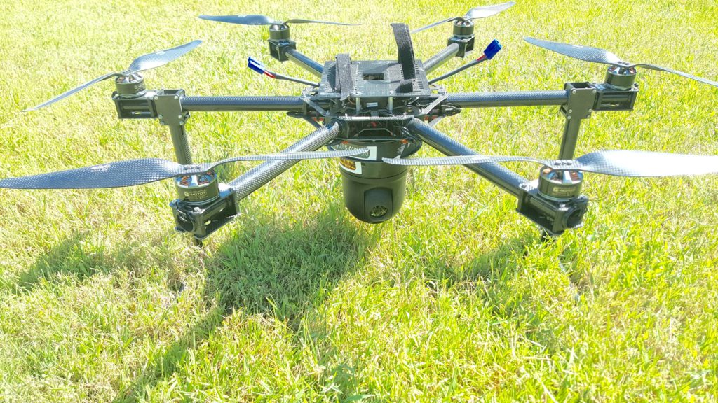
Cameras fixed on vehicles, both manned and unmanned, face diverse challenges. Though the wider field of view might minimize shake effects, factors like vehicle speed, camera type, and terrain conditions play a role in stabilization needs.
Coastal Watch & Maritime Ships
A ship in open waters faces considerable movement. The kind of gyro stabilization needed varies depending on the vessel size and camera’s field of view.
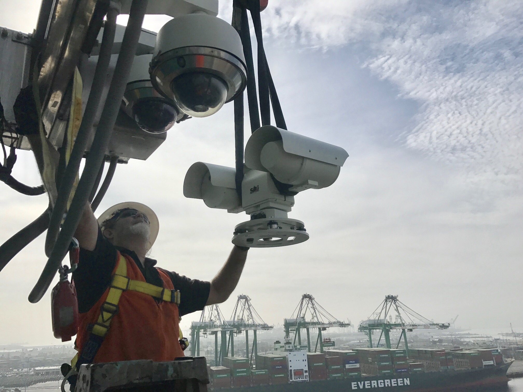
Every scenario has its nuances. At SPI, we pride ourselves on crafting camera and gimbal systems tailored to your needs, balancing performance and cost. Whether it’s pioneering technology, an efficient pointing solution, or a bespoke EO/IR gyro PTZ surveillance system, SPI’s team of engineers and specialists are on hand to collaborate and deliver a solution aligned with your goals and budget.
Resources
- Gyroscopic stabilization minimizes drag on Ruellia ciliatiflora seeds:
- Royal Society Publishing Article – This article examines the aerodynamics of R. ciliatiflora seeds and their gyroscopic stabilization.
- Drone Gyro Stabilization, IMU And Flight Controllers Explained:
- DroneZon Article – An informative piece on the main function of gyroscope technology in drones.
- Shaken not Stirred: A Pilot Study Testing a Gyroscopic Spoon Stabilization Device in Parkinson’s Disease and Tremor:
- NCBI Article – A study on a gyroscopic spoon stabilization device for Parkinson’s Disease patients.
